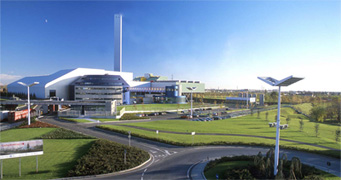
Utilising thermal processes to break down waste into a fraction of its original size, these plants generate baseload renewable energy (i.e. steam which can then be used to generate electricity) and use a flue gas treatment system typically consisting of a scrubbing reactor, a bag filter and sometimes, a catalytic reactor, to reduce the resultant flue gas emission concentrations to well below European Environmental standards.
History
Thermal treatment of waste has existed since humans first discovered fire and has been used throughout history, with the first large scale thermal plant being built in Nottingham, England in 1874. From there plants were built throughout Europe and America helping solve the chronic waste issue faced during the Industrial Age, bringing in the Age of Sanitation. Though these plants helped reduce the amount of waste filling landfills, they were inefficient, and their outputs not used to generate renewable energy.
In the early 1900’s the moving grate combustion system was developed, based on the premise that fuel ignites more easily when an already existing glowing mass is pushed back underneath it.
The concept was further developed over time and the grate proved to be the solution to creating efficient combustion of MSW and similar mixed wastes.

The Danish Energy Statistics report published in 2005 shows that Energy from Waste plants in Denmark produced over 4.8% of the electricity and 13.7% of domestic heat requirements.
According to a Waste-to-Energy Technology report prepared by an independent consultant on behalf of the Western Australian EPA and the WA Waste Authority (2013), to inform the development of the WA EPA’s Section 16e Strategic Advice to the Minister for the Environment in relation to the environmental and health performance of WtE technologies (please refer to Environmental and health performance of waste to energy technologies (EPA Report 1468)), there are over 1000 Energy from Waste plants in operation around the globe, the majority of which use moving grate combustion technology.
How it works
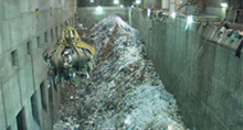
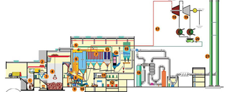
In a typical WtE (or EfW) plant, MSW (Municipal Solid Waste) is brought in by waste collection vehicles and deposited in a waste storage bunker containing the ‘waste crane’. This crane will pick up waste and place it into a feed hopper with a chute to the moving grate, thus ensuring a constant flow of fuel onto the grate. Within the firing chamber though, the manner in which the MSW is managed and brought to combustion is critical to the performance and effectiveness of the plant and to its emissions. By its very nature MSW is not an entirely predictable fuel in its consistency or its constitution. It is therefore this component of the process which is unique to MSW (and similar mixed fuels), creating an optimised, efficient and complete combustion.

Air is supplied via vents below the grate, which ensures the grate is kept at a constant temperature, and also via nozzles directly into the boiler to generate a greater oxygen mix to ensure that complete combustion occurs.
To breakdown organic toxins, during certain parts of the process the flue gas temperature is raised to at least 850 °C. After which it’s then cooled in the superheaters and boiler, transferring the recovered heat to generate steam. This steam can then be sent to steam turbines to generate electricity or used directly by industry as a heat source. Finally the remaining flue gasses are passed through a series of filters, scrubbers and/or reactors to reduce emission concentrations to below the required emission limits.
Bottom Ash, the residue which remains after combustion (typically <10 vol% of the feedstock, depending on the feedstock composition), can be recovered and used as aggregate or further processed to create bricks or pavers.
Typical Stack Emissions for modern WTE facilities
Whilst it is indeed true that in the 1970s and 1980s mass combustion type thermal waste to energy plants were seen as polluting, after the introduction of Maximum Available Control Technology (MACT) regulations implemented in the 1990s by the US EPA and the European Waste Incineration Directive in 2000, by European Environment agencies, the US and European WTE industry invested in retrofitting pollution control systems such that WtE has now become one of the lowest emitters of high temperature processes.
The Table summarises the criteria and performance of the Brescia (Italy) WtE plant as an example. This plant was required to meet stringent Plant Approval emissions limits at the time of design and has since been compared to the EU 2000 limits.
| Stack Emissions | Plant Approval Limits (1993) | Plant Design Data (1994) | EUROPEAN UNION Limits (2000) | Actual Operating Data |
|---|---|---|---|---|
| Particulate Matter | 10 | 3 | 10 | <0,5 |
| Sulphur Dioxide | 150 | 40 | 50 | 10 |
| Nitrogen Oxides (NOx) | 200 | 100 | 200 | 80 |
| Chlorine acid (HCl) | 30 | 20 | 10 | 5 |
| Fluorine acid (HF) | 1 | 1 | 1 | 0.2 |
| Carbon Monoxide | 100 | 40 | 50 | 20 |
| Heavy Metals | 2 | 0.5 | 0.5 | 0.01 |
| Cadmium (Cd) | 0.1 | 0.02 | 0.05 | 0.002 |
| Mercury (Hg) | 0.1 | 0.02 | 0.05 | 0.002 |
| PAH (Polycyclic aromatic hydrocarbon) | 0.05 | 0.01 | - | 0.001 |
| Dioxin (TCDD Teq) ng/Nm3 | 0.1 | 0.1 | 0.1 | 0.01 |

